DIY Drone
Abstract
I built a 70mm DIY drone with a self-built carbon fiber frame and self-printed propellers. Beyond designing these parts, the main challenges were connecting the components, finding fitting motors and a fitting flight controller board, mounting the board on the frame, finding the right battery, connecting the battery to the board, and debugging the board.
Another big challenge was finding and connecting a remote controller, along with wire management and soldering on the very small pads on the board. Debugging was also difficult. It took many iterations to arrive at the right frame and the right propellers, and to find the right technique for soldering on the pads.
I initially planned to add an FPV camera as well, but due to time constraints — since everything else took so long — I decided not to.
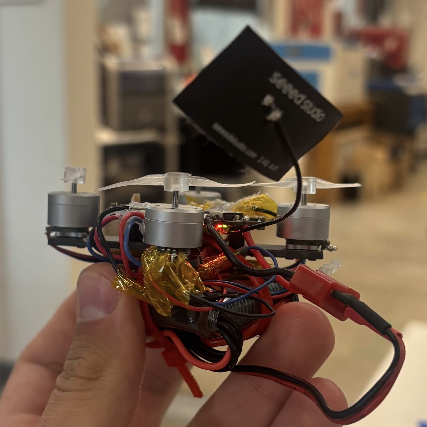
The final build.
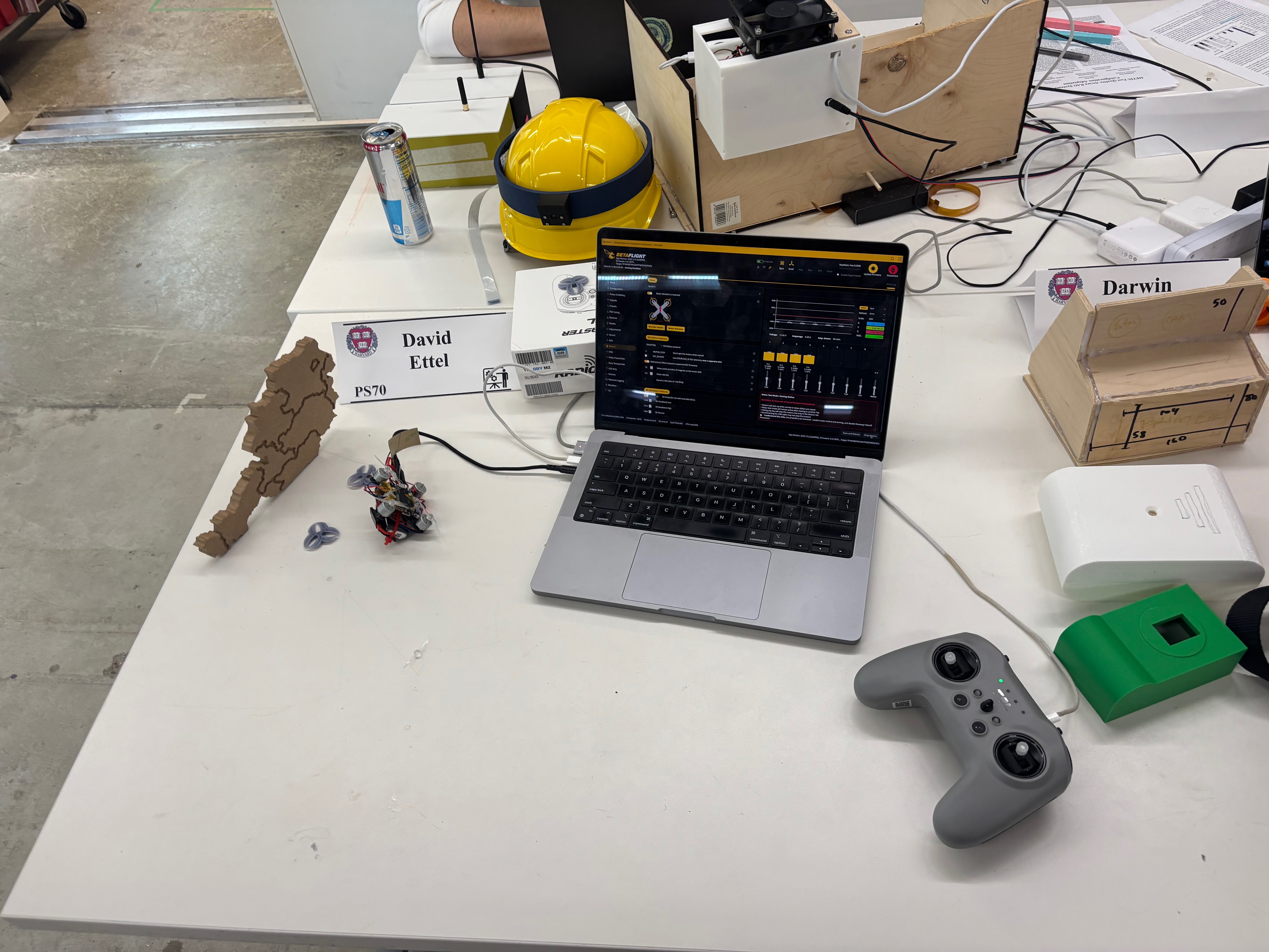
Whole set up: Drone on the left plus flight control debugging software and remote control.
Material List
Every component used in the build, with links to the source.
-
 Happymodel Crux F405HD ELRS AIO (3-in-1 flight controller)DefianceRC ↗
 -
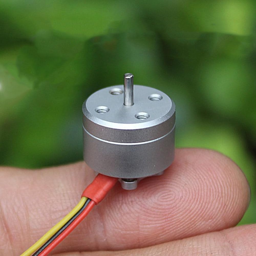 1104 Micro Brushless Motors, 4300 KV (×4) — 1S–3S compatible, FPV racing quadcopter specAmazon ↗
 -
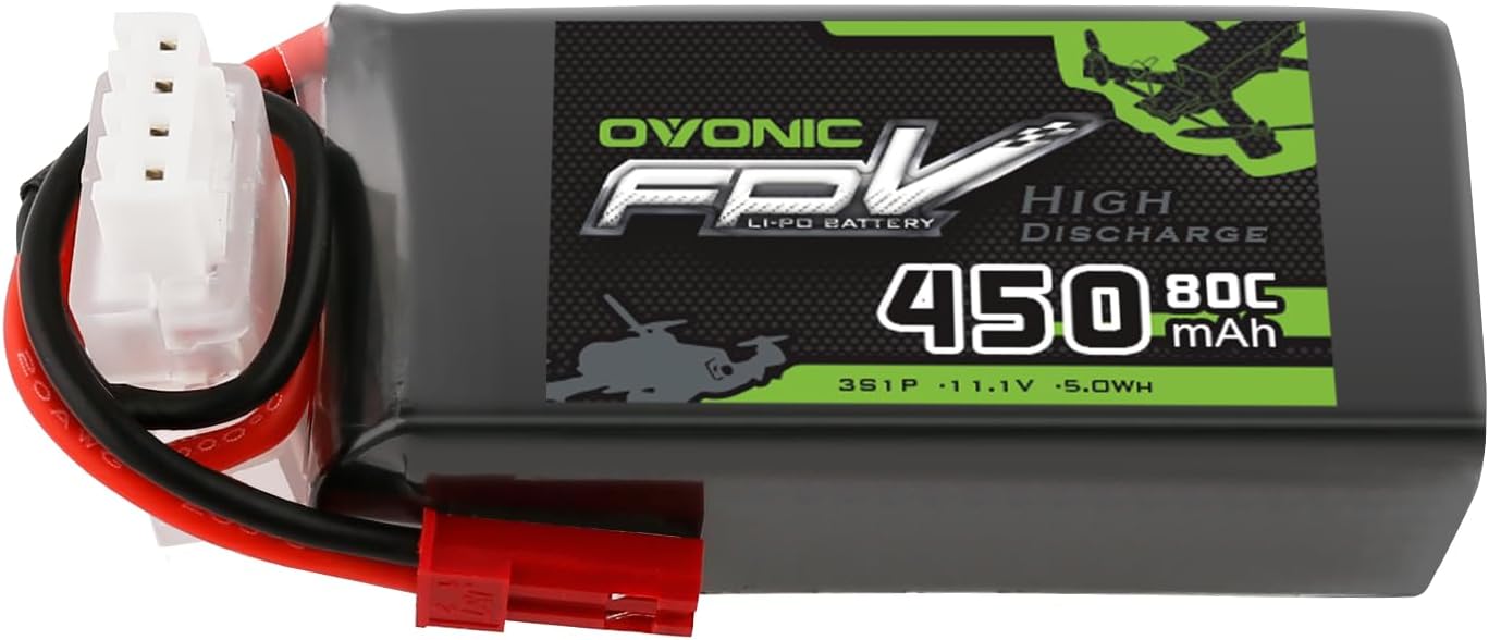 Ovonic 11.1V 450mAh 3S LiPo batteryAmazon ↗
 -
 Battery connector / pigtailsourced from lab
 -
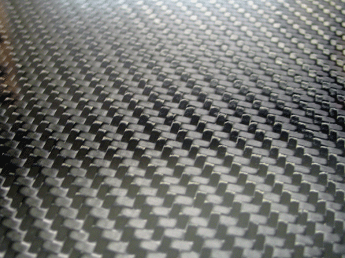 Carbon fiber sheet (frame stock)sourced from lab
 -
 SLA photopolymer resin (3D-printed props)sourced from lab
 -
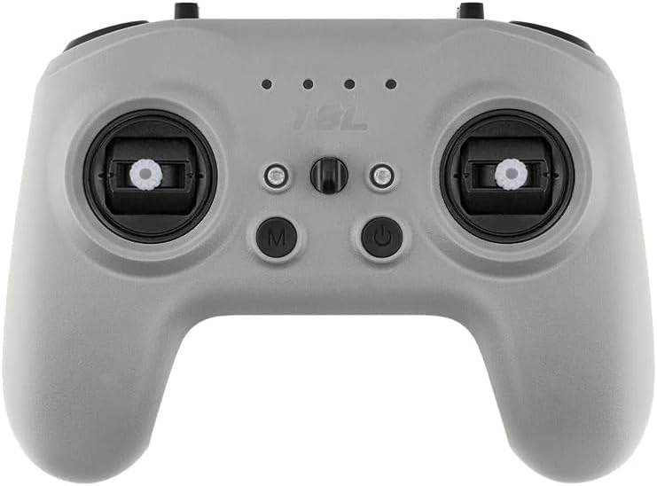 RadioMaster T8L radio controllerAmazon ↗
 -
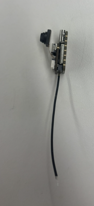 ELRS radio receiver + antennasourced from lab
 -
 Heat-resistant Kapton tapesourced from lab
 -
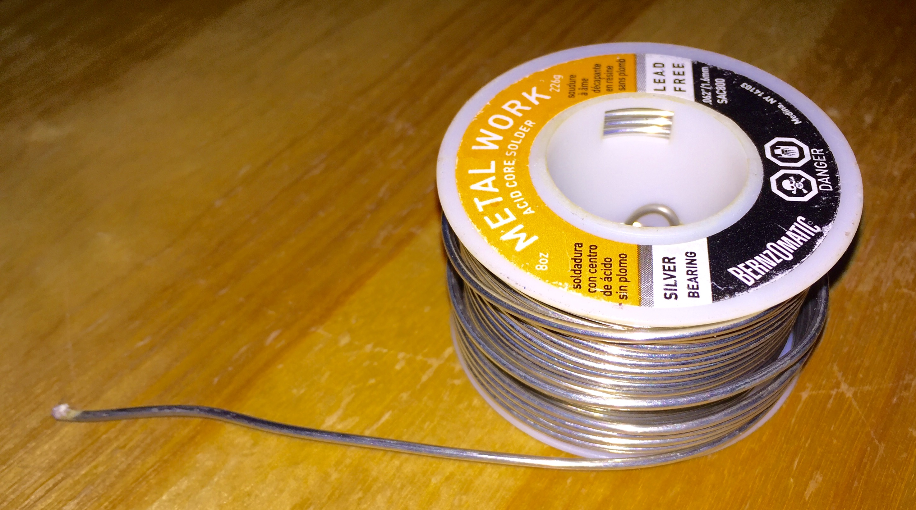 Solder + fluxsourced from lab
 -
 Hot gluesourced from lab
 -
 M2 screws & standoffssourced from lab
 -
 Wiressourced from lab
 -
 Cable binders / zip tiessourced from lab
Thumbnails for the battery connector, carbon fiber, filament, Kapton tape, solder, hot glue, screws, wires, and cable ties are stock photos from Wikimedia Commons under their respective Creative Commons licenses.
Component Diagram
Top-down sketch of the drone with each component labeled. Wires are not shown in the sketch.
Components, disassembled
Choosing the Motors and Flight Controller
Why 70 mm
I picked the 70 mm class because I wanted to iterate as quickly as possible on the frame and the propellers. The smaller the airframe, the cheaper and faster each iteration: less filament per prop, less carbon fiber per frame, less waterjet time, and lower stakes when something snaps or doesn't fly. So I went with the smallest build that could still physically fit four motors, a flight controller, and a battery.
Why I didn't build my own board
I initially thought about building my own flight controller around an ESP32. After looking into it, I dropped that plan for two reasons.
The first reason is loop frequency. A hobby-grade ESP32 flight controller typically runs its gyro / PID feedback loop somewhere between 250 Hz and 1 kHz, limited by I²C/SPI bus speed to the IMU and by firmware overhead. A 70 mm-class drone is small, light, and twitchy — that loop rate is not fast enough to stabilize it reliably. A commercial flight controller running Betaflight on a dedicated STM32 F4/F7/H7 MCU runs the gyro loop at 8 kHz by default (see Betaflight's PID & looptime documentation), with modern F7/H7 boards going up to 32 kHz gyro and 16 kHz PID — roughly 8× to 30× faster than what a DIY ESP32 board realistically achieves.
The second reason is the firmware itself. A flight controller isn't just a microcontroller and an IMU — it needs gyro filtering, a PID feedback loop, motor mixing, an ESC protocol driver (DShot), a receiver protocol driver (ELRS/CRSF), failsafe logic, and tuning. Writing all of that from scratch is a massive project on its own, and Betaflight has had years of community work poured into the filtering and tuning alone.
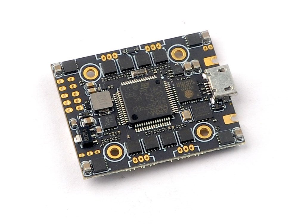
So I went with an All-In-One (AIO) board that ships with Betaflight preloaded. I picked the Happymodel Crux F405HD ELRS AIO specifically for price and availability — it was the cheapest 70 mm-class AIO I could actually get hold of with the ELRS receiver already integrated.
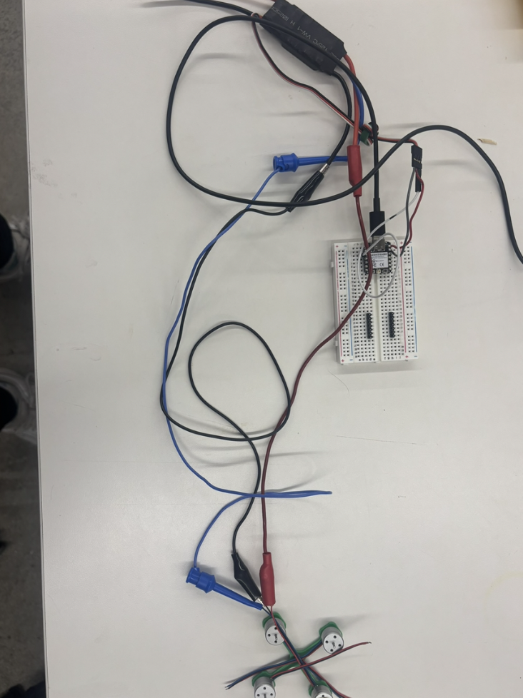
Earlier attempts & mounting
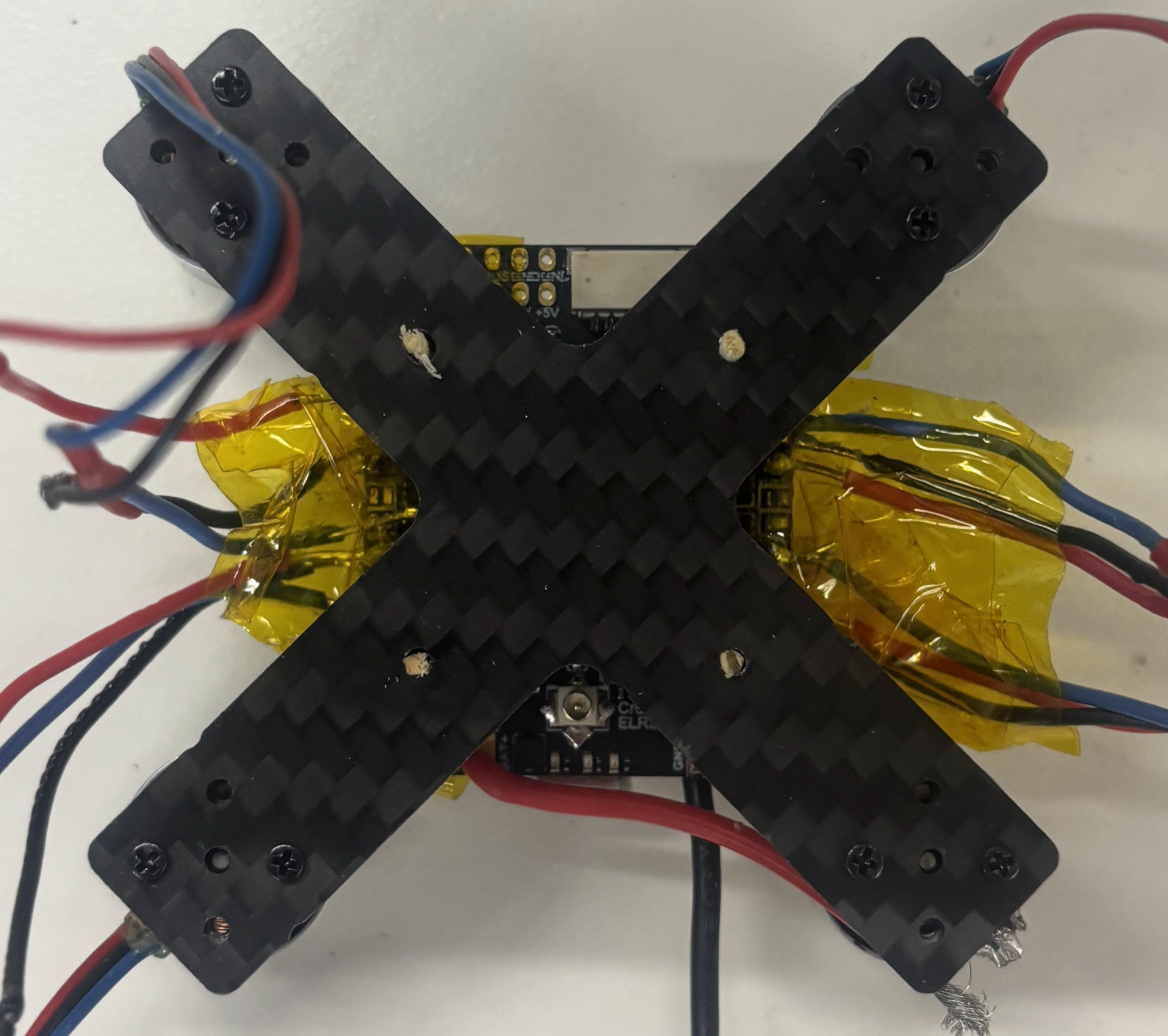
Before settling on the AIO, I briefly experimented with a separate flight controller + standalone ESC stack, but abandoned that direction (see the first two photos below).
The third photo shows the AIO mounted on the (earlier X-shaped) carbon fiber frame with matches as standoffs. I originally wanted to mount the board with screws, and that's what I used in the earlier PLA frame iterations. On the carbon fiber frame, though, the mount holes came out too small for the screws — a problem that persisted even after I significantly enlarged the holes — and I stopped trying to fix it after the waterjet stopped working.
Frame Iterations
The frame went through several prototypes. The picture below shows a selection of them — I had more, but not all survived. They are arranged chronologically from left to right.
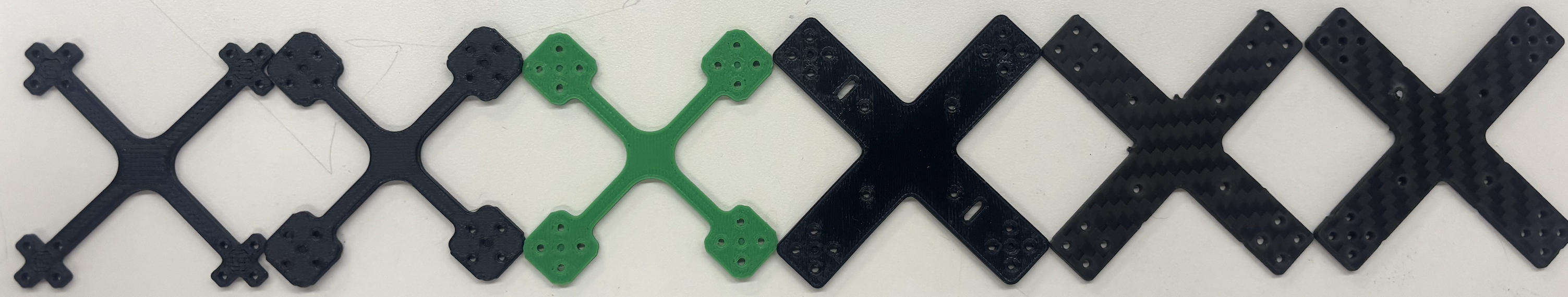
Selection of frame prototypes, chronological left → right.
- v1 — naive PLA print. A first pass just to see the geometry in physical form. No reinforcement, no thought to motor-shaft clearance.
- v2 — reinforced holes & motor-shaft sinks. Added more material around the mounting holes so they wouldn't crack, and a small sink on each arm because I realized the motor shaft needs a bit of extra clearance at its bottom.
- v3 — rotated motor-mount pattern. Turned the motor mounting holes 45° so the motor wires exit in a direction that doesn't fight the arm geometry.
- v4 — AIO mounting holes & battery slits. Added mounting holes for the AIO flight controller and slits for battery straps. The slits forced the arms to get wider to keep enough material around them.
- v5+ — switch to carbon fiber. PLA frames vibrate too much and bend/break too easily for a real drone, so I switched the stock to carbon fiber. I dropped the battery-strap slits again on this version — I now strap the battery diagonally with cable ties instead.
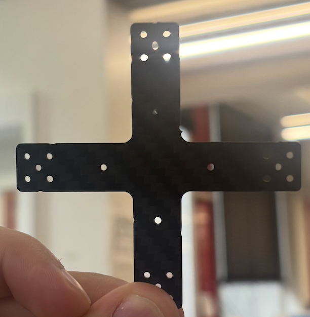
- Final — waterjet-cut carbon fiber. Reintroduced the motor-shaft "sinks" from v2, but because the part is waterjet-cut from a flat sheet they can't be partial-depth recesses — they have to be actual through-holes. This is the geometry in finalframe.dxf.
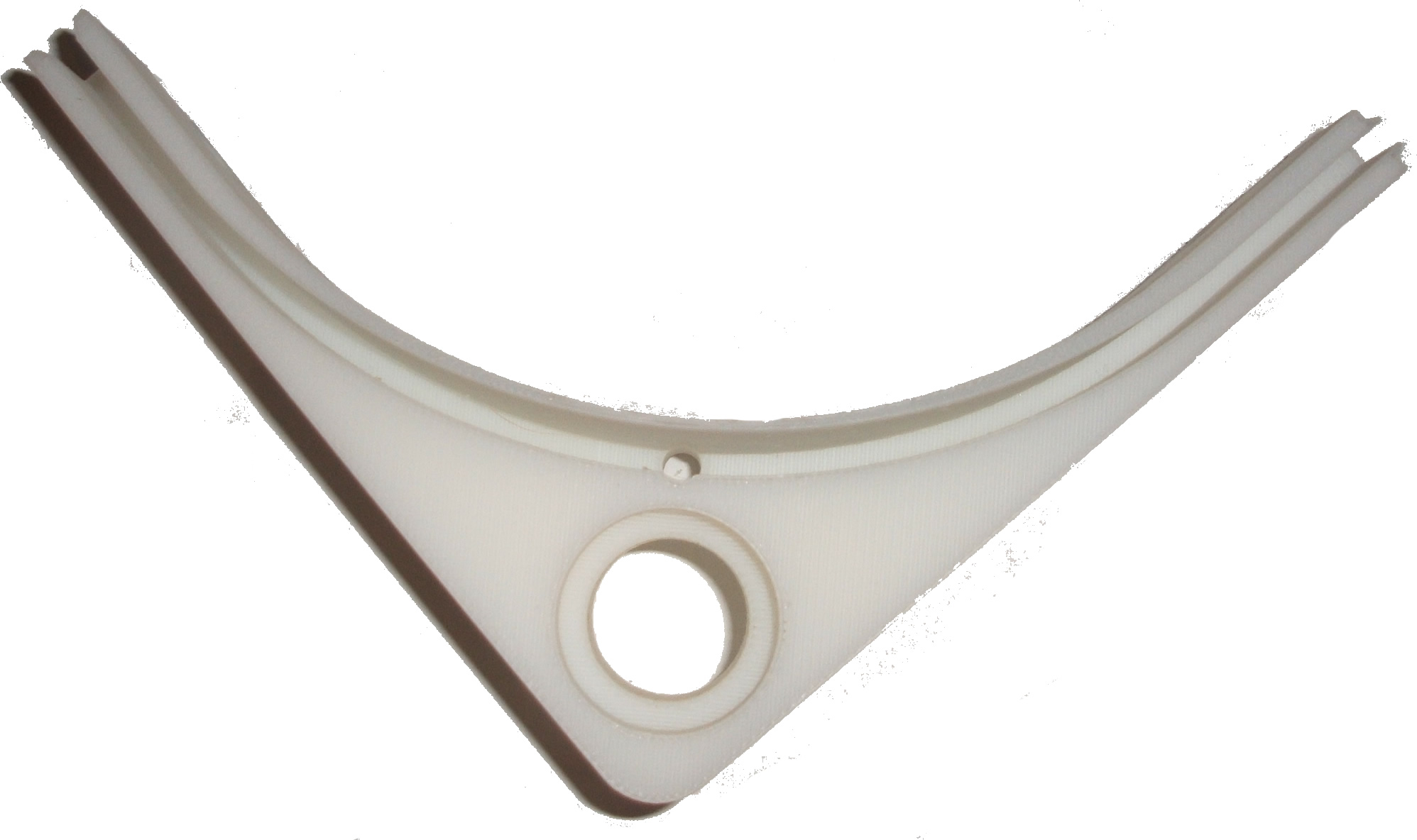
Final frame design

Final waterjet-cut frame geometry (finalframe.dxf).
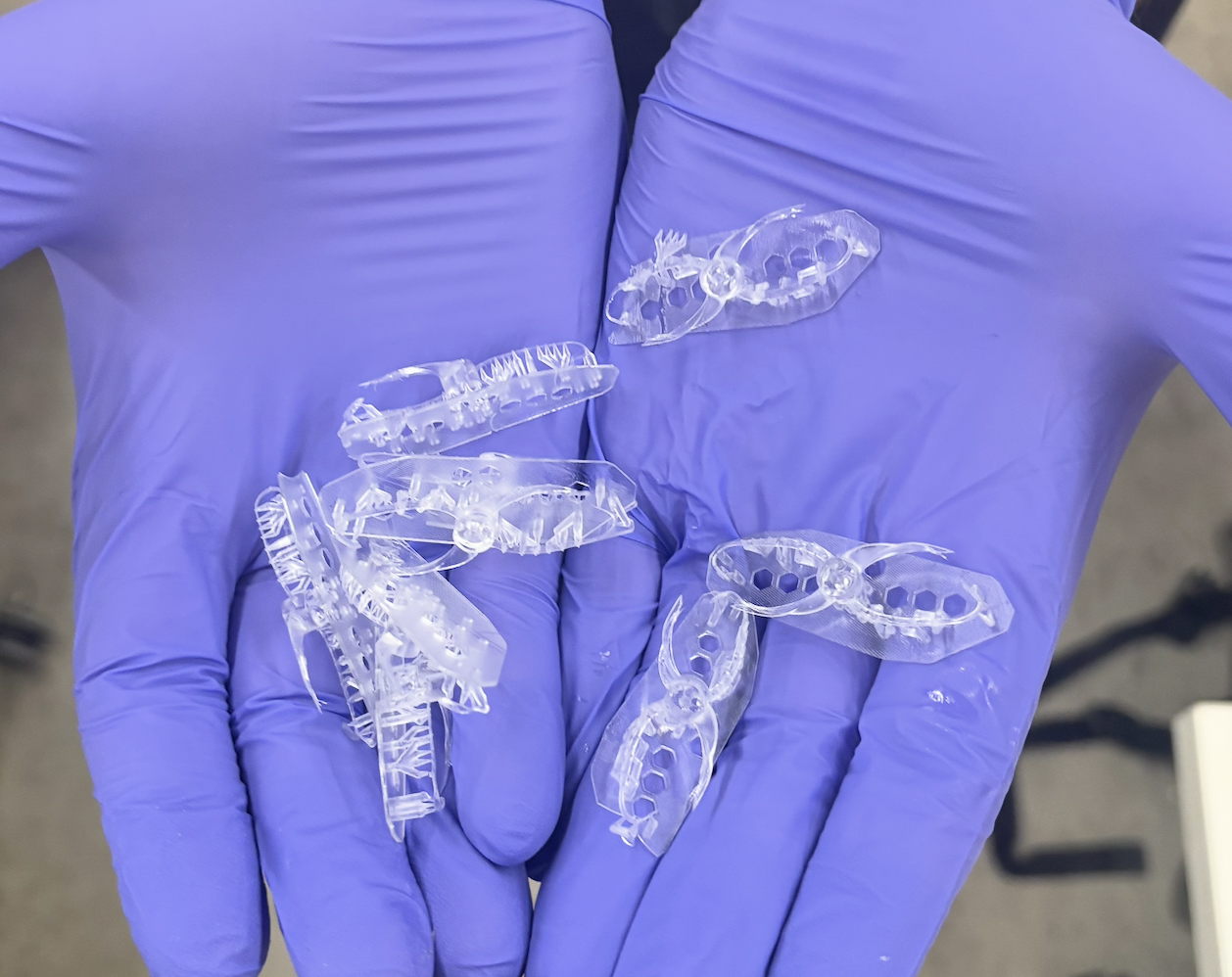
Propellers
I decided to 3D-print the propellers myself instead of ordering them. The picture below shows the versions I kept, chronologically left → right. There were many more iterations than this; most of them never came out as proper propellers and are shown further down.
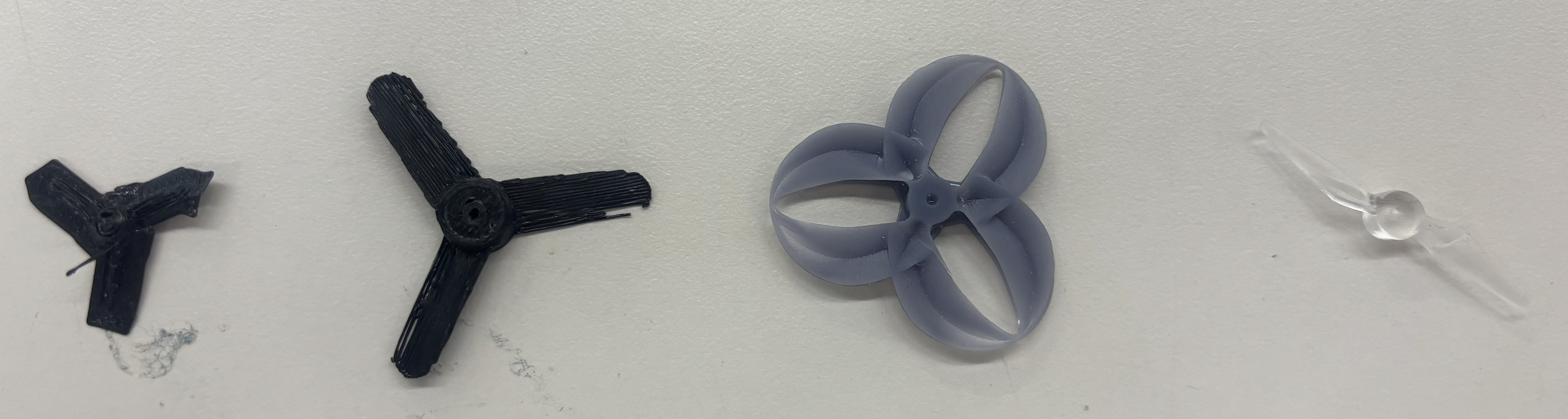
Propeller iterations, chronological left → right.
- v1 — Prusa FDM, original scale. The leftmost propeller. The Prusa simply didn't have the resolution to resolve the blade geometry — the print was nowhere close to what the design called for.
- v2 — Prusa FDM, scaled up. Scaled up to give the printer more room. Still too coarse to come out smooth, and the blades remained too thin for the FDM nozzle. This was the cue to abandon FDM and switch print technologies.
- v3 — resin, downloaded CAD. Before redesigning I read Popișter (2025), "Experimental Study of Comprehensive Performance Analysis Regarding the Dynamical/Mechanical Aspects of 3D-Printed UAV Propellers and Sound Footprint", which fabricated six propeller variants in TPU, PETG, and photopolymer resin (in toroidal and tri-blade configurations) and tested thrust, acoustic emissions, compression strength, and motor thermal load. The main takeaway for me: resin propellers produced the highest thrust, and 3D-printed polymer propellers are viable for hobbyist UAVs. The paper doesn't release the CAD, so I searched the web for a comparable design — this is the third propeller in the picture. The surface came out far smoother on resin, which reinforced the print-tech decision. The geometry itself, however, didn't make much aerodynamic sense — visible in the print and obvious once it was spun up on the actual motor.
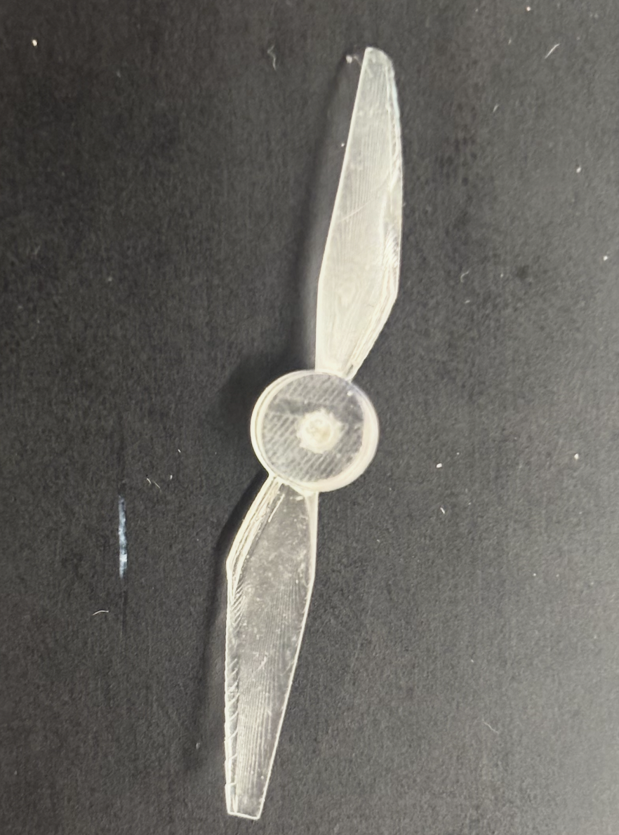
- v4 — two-blade, Claude-generated STL (final). Between v3 and v4 I iterated with the Ultimate Toroidal Propeller Generator — an open-source OpenSCAD project that produces parameterized toroidal propeller STLs (blade count, CW/CCW rotation, hub geometry, NACA airfoil profiles, chord lengths, and attack angles at multiple keyframes along a Catmull–Rom toroidal path). The resin printer kept struggling with the thin connecting loops of the toroidal geometry, though. So I switched back to a conventional two-blade design and had Claude Code generate the STL directly — which it did surprisingly well. I bumped blade thickness and edge thickness so the resin printer could resolve the features, then tested different attack angles and support configurations. The fourth version — embedded below as finalpropeller.stl — turned out to displace air notably better in empirical tests spun up on the actual motor. Final specs: 40 mm prop diameter, 1.5 mm shaft (hub) bore.
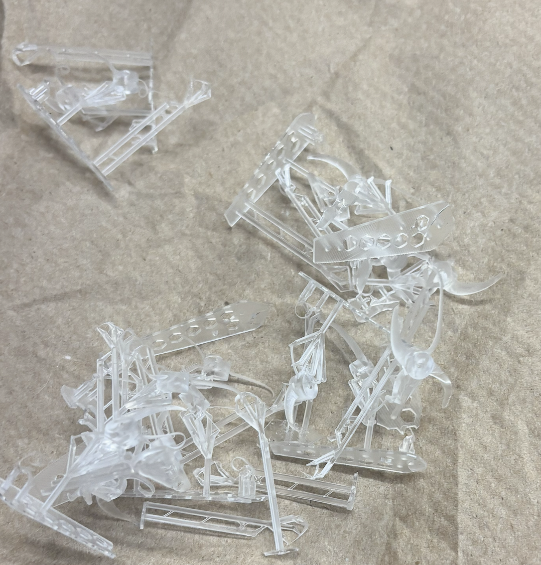
Failed prints
Most resin propeller iterations did not actually print as proper propellers — thin features, under-supported overhangs, and toroidal joins that the printer just couldn't resolve.
3D Model
Click and drag to rotate • Scroll to zoom • Right-click drag to pan
Soldering Technique
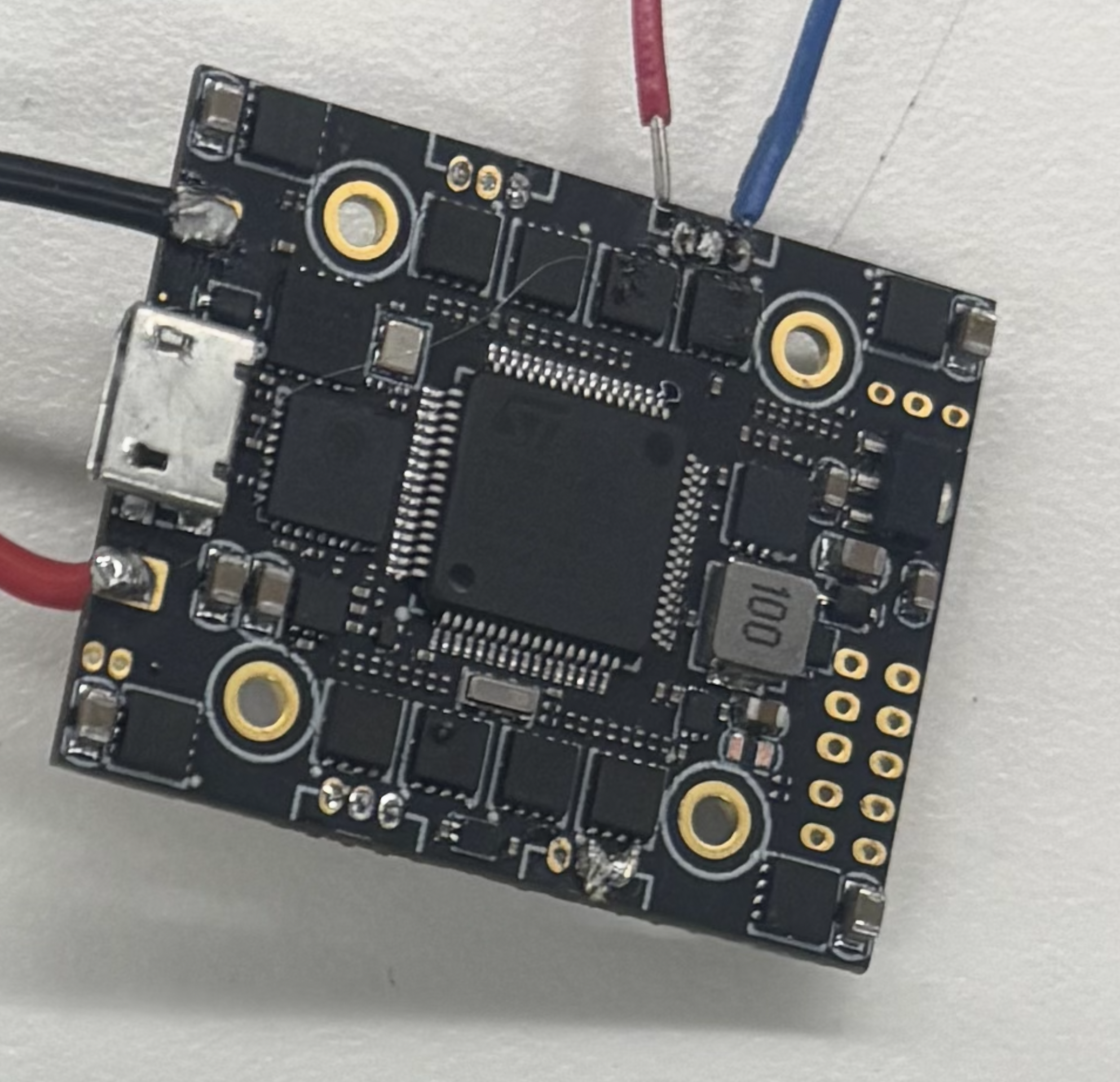
The AIO board, close-up of the solder pads.
The soldering pads on the AIO board are extremely small and have almost no space between them. This made soldering extremely difficult. I spent hours on them. I asked Aadit and Bobby for help and both of them tried for hours too — we all failed.
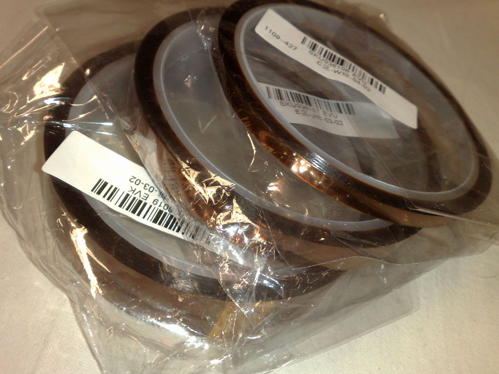
Then I did some research online and learned about heat-resistant tape (Kapton / polyimide tape, pictured below). I used the tape to cover the neighboring pads, and from that point on the soldering became child's play (not really, but much easier).
Kapton (polyimide) heat-resistant tape — stock photo. By Dsimic, via Wikimedia Commons, CC BY-SA 3.0.
I also had to solder wires together and re-solder connections to the motors. In that process I used heat-shrinks to insulate and tidy the joints. And because my connections to the board still kept breaking under vibration, I used hot glue and tape to reinforce them.
Battery
Ovonic 11.1V 450mAh 3S LiPo — the battery I ended up ordering.
We did not have an 11.1V battery in lab. I initially tried using 3.7V single-cell batteries, but the form factor that gave the needed capacity was simply too big for the drone. That is why I ordered the multi-cell 3S LiPo above.
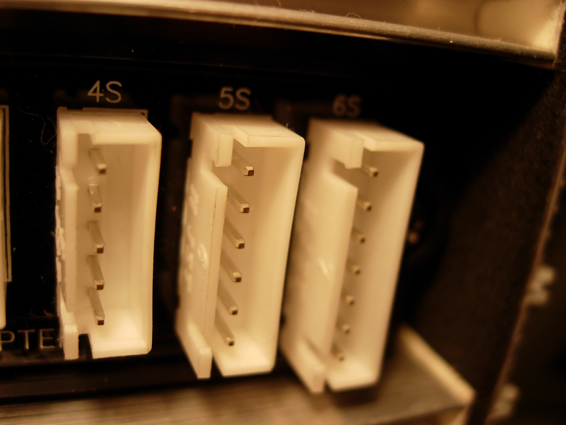
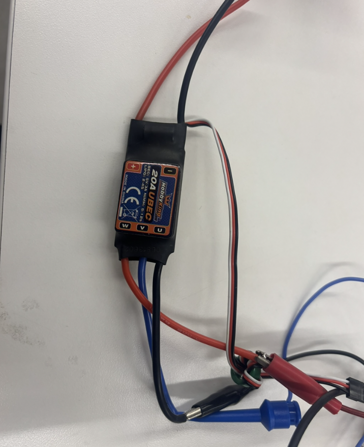
Nathan gave me a short safety training on how to handle LiPos — puncture, short, thermal runaway, fire risk — and gave me the LiPo balance charger below to charge and discharge the pack safely.
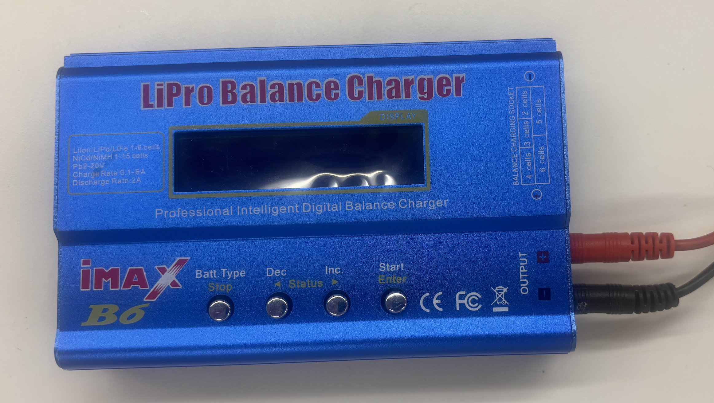
LiPo balance charger (loaned from the lab) — for charging and safe discharging.
One of the bigger issues was actually connecting the battery to the board reliably and safely. Soldering the battery leads directly to the FC is both unsafe and unwise — every plug/unplug cycle stresses the joint, and a shorted or damaged pack with no way to disconnect is a fire waiting to happen. So I built a custom wire-to-socket-pin connection instead, visible in some of the photos further up the page.
For mounting, I used cable binders to strap the battery to the frame diagonally — the solution that replaced the earlier battery-strap slits in the PLA frame iterations.
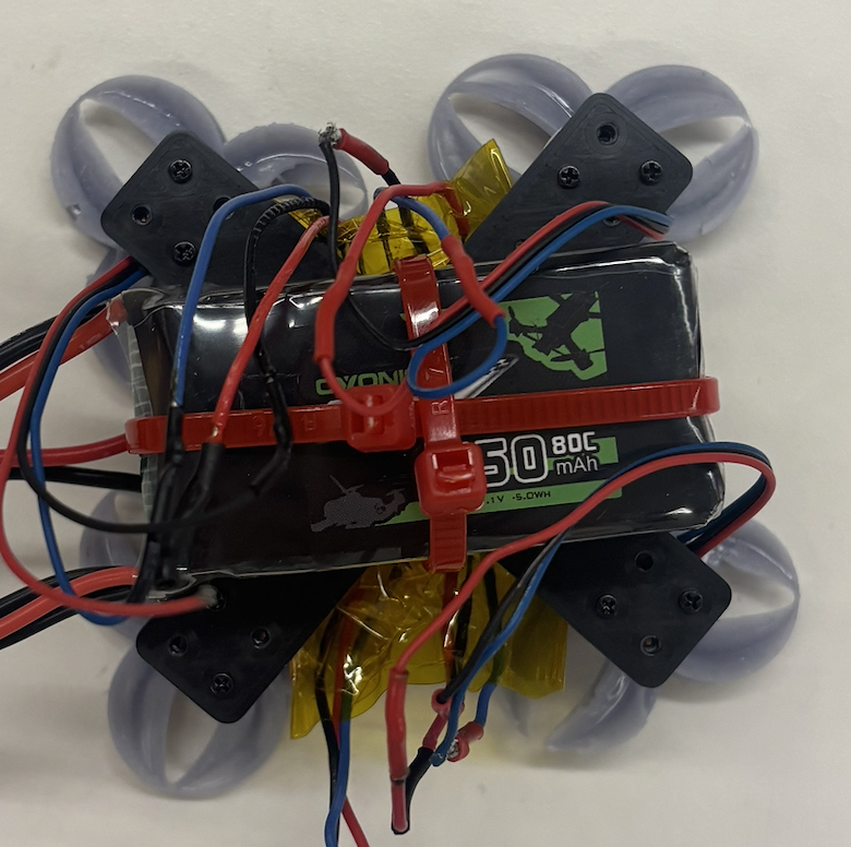
Battery strapped diagonally to the carbon fiber frame with cable binders.
Controlling the Drone
Betaflight
Betaflight is the open-source firmware that runs on the AIO. It handles gyro filtering, the PID feedback loop, motor mixing, the DShot ESC protocol, and the receiver protocol, and exposes everything through the Betaflight Configurator app — where you flash firmware, map motors, set gyro orientation, configure failsafe, and tune PIDs. I used Betaflight heavily for debugging, especially the motors (motor mapping, spin direction, identifying dead or mis-wired motors via the Motors tab).
Betaflight walkthrough.
RadioMaster T8L
RadioMaster T8L — compact ExpressLRS 2.4 GHz transmitter (product page, official manuals).
The T8L is a screenless ExpressLRS 2.4 GHz radio that bound directly to the AIO's onboard ELRS receiver. It's configured through RadioMaster's web-based UI rather than an on-device menu.
Why not just use an ESC or a laptop to fly?
An ESC alone only drives a single motor at a commanded throttle — there's no controller in the loop to mix yaw, pitch, and roll across four motors or to react to the gyro, so it can't stabilize a drone. A laptop tethered to the FC over USB can arm the board and ramp motors on the bench (useful for testing), but as an in-flight controller it fails on three counts: USB-serial latency is too high to feed an 8 kHz PID loop responsively, keyboards and mice can't smoothly modulate throttle and stick deflection, and there's no wireless link — you'd have to chase the drone with the laptop attached. A dedicated 2.4 GHz radio solves all three.
Challenges
The biggest blocker right now: three of my four motors failed, so I have not been able to actually get the drone in the air. I have ordered new motors and expect the drone to fly as soon as they arrive.
The build hit a lot of other walls along the way, most of which are documented in their own sections above. To summarize: the flight controller pads are tiny and almost impossible to solder cleanly until I learned the Kapton-tape masking trick (with hours of failed attempts before that, including help from Aadit and Bobby). The frame went through six iterations from naive PLA to waterjet-cut carbon fiber, and even the final carbon frame had mount holes that came out too small for screws (which is why the AIO ended up mounted with matches as standoffs on the X-frame). The propellers went through four kept versions plus many failed prints — FDM didn't have the resolution, resin worked but the toroidal geometry kept failing at thin joins, until I converged on a beefier two-blade design. The battery wasn't available in the right voltage in lab; single-cells were too bulky, so I ordered a 3S LiPo, learned to handle it safely with Nathan's training, and built a custom wire-to-socket-pin connector because soldering battery leads directly to the FC is a fire risk. And the overall debugging — power, signal, firmware, mechanical — was the kind of "nothing works, isolate one variable at a time" grind that ate most of the time on this project.
Separately: waterjet-cutting carbon fiber has very different kerf behavior than 3D printing, so holes and slots come out tighter or looser than the CAD; I had to adjust dimensions in the DXF to compensate, and even then the screw holes were the wrong size.
Future Outlook
- FPV. Adding the FPV camera and 5.8 GHz video transmitter (VTX) that I dropped from this build for time. With a small FPV cam on the front of the frame, a VTX wired into the AIO's video pad, and FPV goggles on the pilot side, the drone becomes actually flyable beyond line-of-sight and unlocks the whole reason small quads are fun to build in the first place.
- Tuning PIDs properly once the airframe is reliable
- Iterating on prop design with the data I now have
- Possibly a larger build with what I've learned about kerf, soldering, and battery handling
Demo video
Demo video: explanation and flight attempt plus one motor rotating at fair.